The Paths tool allows you to create complex geometric shapes called «Bézier Curves», a bit like the Free Selection tool, but with all the adaptability of vectorial curves.
You can edit your curve, you can paint with your curve, or even save, import, and export the curve. You can also use paths to create geometrical figures. Paths have their own dialog box: the Paths Dialog.
See also the Paths concept.
Paths can be turned into Vector layers. A Vector layer is a special kind of layer that displays a path, possibly consisting of several parts, including their selected fill and stroke attributes.
Esistono diverse possibilità per attivare lo strumento:
-
From the main menu: → .
-
Facendo clic sull'icona dello strumento
 nel pannello strumenti.
 -
By pressing the B keyboard shortcut.
![[Nota]](images/note.png)
|
Nota |
|---|---|
|
The status bar at the bottom of the image window will show relevant tips about the possible modifiers you can use when working with paths. |
- Maiusc
-
Questo tasto ha molte funzioni in base al contesto. Vedere le opzioni per maggiori informazioni.
- Ctrl ; Alt
-
Tre modalità sono disponibili per lo strumento Tracciati: Progetta, Modifica e Sposta. Il tasto Ctrl commuta tra Progetta e Modifica. Il tasto Alt (o Ctrl+Alt) commuta tra Progetta e Sposta.
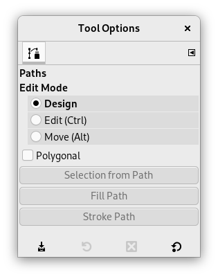
Normally, tool options are displayed in a window attached under the Toolbox as soon as you activate a tool. If they are not, you can access them from the main menu through → → which opens the option window of the selected tool.
- Modalità Modifica
-
- Progetta
-
La modalità predefinita di questo strumento è Progetta. Basta fare clic per disegnare il tracciato. Poi basta fare clic sui punti di controllo e trascinarli per spostarli. I punti di controllo sono uniti da segmenti.

I numeri sono i passi necessari per disegnare un tracciato rettilineo a due segmenti.
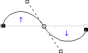
I segmenti curvi possono essere facilmente creati trascinando un segmento o un nuovo nodo. Le frecce blu indicano la curva. Quando si trascina per piegare la curva appaiono due piccole maniglie.
![[Suggerimento]](images/tip.png)
Suggerimento To quickly close the curve, click on the initial control point. If you want to reposition the start node, hold Shift and click to deselect the end node, then move the start node.
You can use the button or
 the Path to Selection button
in the Paths dialog to convert the path to a Selection.
the Path to Selection button
in the Paths dialog to convert the path to a Selection.
Suggerimento Se sono visibili le due maniglie, esse lavorano simmetricamente. Rilasciando il tasto del mouse si può spostarle singolarmente. Il tasto Maiusc forza nuovamente l'accoppiamento delle maniglie.
In modalità Progetta sono disponibili diverse funzioni:
Inserimento di un nuovo nodo: quando si preme Ctrl e si passa sopra il tracciato esistente con il mouse, il puntatore del mouse diventa un segno '+'. Facendo clic si crea un nuovo nodo del tracciato nel punto dove il puntatore del mouse passa sopra al tracciato.
Spostamento di uno o più nodi: su un nodo, il puntatore del mouse diventa una croce a quattro punte. Si può puntare e trascinare. Premendo il tasto Maiusc è possibile selezionare più nodi e spostarli trascinandoli. Premendo Ctrl+Alt si può spostare l'intero tracciato come una selezione.
Modifica maniglie: prima è necessario modificare un nodo, poi appare una maniglia: trascinandola si piega la curva. Tenendo premuto il tasto Maiusc si passa alla manipolazione simmetrica delle maniglie.
Modifica del segmento: quando il puntatore del mouse passa sopra un segmento, diventa una croce a quattro punte. Trascinandola si piegherà il segmento. Non appena la si muove appariranno delle maniglie alle estremità del segmento. Premendo il tasto Maiusc si passa alle maniglie simmetriche.
Aggiunta di un nuovo sottotracciato: premendo Maiusc e passando sopra con il puntatore del mouse fuori dal tracciato esistente, il puntatore del mouse diventa un quadrato. Facendo clic si inizierà un sottotracciato non connesso ad altre curve, ma che verrà considerato parte del tracciato.
- Modifica (Ctrl)
-
Modifica fornisce le funzioni che non sono disponibili in modalità Progetta. Questa modalità consente di lavorare sul tracciato esistente. Fuori dal tracciato il puntatore diventa un piccolo cerchio crociato e non si può fare nessuna modifica del tracciato.
Aggiungere un segmento tra due nodi: fare clic su di un nodo ad un capo del tracciato per attivarlo. Il puntatore avrà la forma di un simbolo di unione. Fare clic su di un altro nodo per collegare i nodi. Utile se si vuole collegare componenti non chiusi.
Rimuovere un segmento da un tracciato: mentre si preme la combinazione di tasti Maiusc+Ctrl, puntare ad un segmento. Il puntatore cambia in un segno "-". Fare clic per eliminare il segmento.
Aggiungere un nodo al tracciato: puntare ad un segmento. Il puntatore cambia in "+". Fare clic dove si vuole piazzare il nuovo punto di controllo.
Rimuovere un nodo: mentre si preme la combinazione di tasti Maiusc+Ctrl, puntare ad un nodo. Il puntatore cambia in un "-". Fare clic per eliminare il nodo.
Aggiungere una maniglia ad un nodo: puntare su di un nodo. Il puntatore diventa una piccola mano. Trascinare il nodo: appare la maniglia. Premendo il tasto Maiusc si commuta in maniglie simmetriche.
Rimuovere una maniglia da un nodo: mentre si preme la combinazione di tasti Maiusc+Ctrl, puntare su una maniglia. Il puntatore non cambia in un "-" come ci si aspetterebbe e rimane una manina. Fare clic per eliminare la maniglia.
![[Attenzione]](images/caution.png)
Attenzione Non viene generato nessun avvertimento prima della cancellazione di un nodo, di un segmento o di una maniglia.
- Move (Alt)
-
La modalità sposta permette di spostare una o tutte le componenti di un tracciato. Basta semplicemente fare clic sul tracciato e spostarlo.
Se ci sono più componenti, verrà spostato solo il selezionato. Se si fa clic e si trascina fuori il tracciato, tutte le componenti vengono spostate. Premendo il tasto Maiusc si commuta tra la possibilità di spostare tutti i componenti o solo il selezionato.
- Poligonale
-
Con quest'opzione, i segmenti sono solo lineari. Le maniglie non sono disponibili ed i segmenti non vengono curvati spostandoli.
- Selezione dal tracciato
-
This button allows creation of a selection that is based on the path in its present state. This selection is marked with the «marching ants» . Note that the path is still present: the current tool is still the path tool and you can modify this path without modifying the selection that has become independent. If you change tools, the path becomes invisible, but it persists in the Paths Dialog and you can re-activate it.
Se il tracciato non è chiuso, GIMP lo chiuderà con una linea diritta.
Come dice la finestrella di aiuto a scomparsa, premendo il tasto Maiusc mentre si fa clic sul tasto, aggiungerà la nuova selezione ad una preesistente. Premendo invece il tasto Ctrl si sottrarrà la selezione da una esistente e la combinazione di tasti Maiusc+Ctrl intersecherà le due selezioni.
- Create New Vector Layer
-
This command creates a Vector Layer from the current path. A vector layer remembers its stroke and fill settings and can have Layer Effects applied to it.
- Enable Fill
-
When checked the current path will be filled based on the settings below.
This setting only takes effect if the path being edited is attached to a vector layer. For filling paths not connected to a layer use Fill Paths.
- Colore pieno
-
If this is selected, you can choose what color is used to fill the path by pressing the color button.
- Motivo
-
If this is selected, a pattern will be used to fill the path. You choose another pattern by clicking the resource button or by typing the name of the pattern.
- Antialiasing
-
Enabling this setting allows you to remove or reduce the aliasing effect that can show up on borders.
For more information, see Anti-aliasing in the Glossary.
- Enable Stroke
-
When checked the current path will be stroked based on the settings below.
This setting only takes effect if the path being edited is attached to a vector layer. For stroking paths not connected to a layer use Stroke Paths.
- Colore pieno
-
If this is selected, you can choose what color is used to stroke the path by pressing the color button.
- Motivo
-
If this is selected, a pattern will be used to stroke the path. You choose another pattern by clicking the resource button or by typing the name of the pattern.
This is distinct from the Dash pattern. If you select one of the two color options with no dash pattern, an unbroken line is drawn in the color set in the Toolbox. If you select Pattern with no dash pattern, an unbroken line is drawn with the pattern set in the Toolbox. If you select a line with a dash pattern, the color or pattern is still determined by the color or pattern set in the Toolbox. That is, if you have a marbled pattern set in the Toolbox, and select Pattern and dashed lines as Dash pattern, the dashes are drawn in the marbled pattern.
- Antialiasing
-
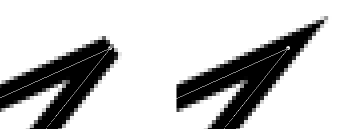
Enabling this setting allows you to remove or reduce the aliasing effect that can show up on borders.
Curved strokes or strokes drawn at an angle may look jagged or stair-stepped. The anti-aliasing option smooths them out.
For more information, see Anti-aliasing in the Glossary.
- Larghezza linea
-
You can set the width of the stroke using the text box. The default unit is pixels, but you can choose another unit with the drop-down list button.
- Cap style
-
Choose the shape of the ends of an unclosed path, which can be Butt, Round or Square.
- Join style
-
You can choose the shape of the path corners by clicking on Miter, Round or Bevel.
- Miter limit
-
When two segments of a path come together, the mitering of the corner is determined by the Miter Limit. If the strokes were wide, and no mitering were done, there would be pointed ends sticking out at the corner. The Miter Limit setting determines how the gap, formed when the outer edges of the two lines are extended, will be filled. You can set it to a value between 0.0 and 100.0, by using the slider or the associated text box and its arrows.
- Motivo tratteggio
-
On the pixel level, a dashed line is drawn as a series of tiny boxes. You can modify the pattern of these boxes. The black area with thin vertical lines represents the pixels of the dash. If you click on a black pixel, you remove it from the dash. If you click on a white pixel, you add it to the dash. The gray areas indicate how the pattern will be repeated when a dashed line is drawn.
- Dash preset
-
Instead of making your own dash pattern, you can choose one from the drop-down box. This pattern will then be displayed in the Dash pattern area, so you can get an idea of how it will look.
When right-clicking on path elements, like anchors or segments, a context menu will appear, the contents of which depends on the item you clicked on. The following commands may be shown in the context menu.
- Delete Anchor
-
This command deletes the selected anchor and connects the segments before and after it.
- Shift Start
-
This command shifts the start anchor to the selected anchor. The start anchor is where stroking starts. The start anchor has a pointy side indicating the stroking direction. This can be useful when you want to wrap Text along Path.
Shifting the start anchor on open strokes may insert a new segment connecting the previous endpoints, and removes the segment leading into the new start anchor.
- Insert Anchor
-
This command adds a new anchor on the selected spot on the segment.
- Elimina segmento
-
This command deletes the selected segment. This will create an opening in your path.
- Reverse Stroke
-
This reverses the direction of the stroke. The shape of the start anchor will reflect the direction of the stroke. The pointy side is the direction it will go to when stroking.


