The Paths tool allows you to create complex geometric shapes called « Bézier Curves », a bit like the Free Selection tool, but with all the adaptability of vectorial curves.
You can edit your curve, you can paint with your curve, or even save, import, and export the curve. You can also use paths to create geometrical figures. Paths have their own dialog box: the Paths Dialog.
See also the Paths concept.
Paths can be turned into Vector layers. A Vector layer is a special kind of layer that displays a path, possibly consisting of several parts, including their selected fill and stroke attributes.
There are different possibilities to activate the tool:
-
From the main menu: → .
-
By clicking the tool icon
 in the Toolbox.
-
By pressing the B keyboard shortcut.
![[Note]](images/note.png)
|
Note |
|---|---|
|
The status bar at the bottom of the image window will show relevant tips about the possible modifiers you can use when working with paths. |
- Shift
-
Cette touche a de multiples fonctionnalités dépendant du contexte ; reportez vous à la section des Options pour plus de précision.
- Ctrl ; Alt
-
L’outil Chemin propose trois modes pour travailler sur les chemins : Tracer, Édition et Déplacer. Avec la touche Ctrl vous basculez entre Tracer et Édition, et avec les touches Alt (ou Ctrl+Alt) vous basculez entre Tracer et Déplacer.
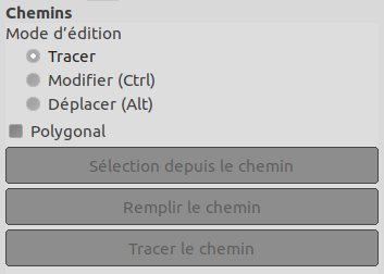
Normally, tool options are displayed in a window attached under the Toolbox as soon as you activate a tool. If they are not, you can access them from the main menu through → → which opens the option window of the selected tool.
- Mode Édition
-
- Design
-
Normalement l’outil se trouve constamment dans le mode Tracer. Les segments d’un chemin se dessinent à la souris par des clics successifs. Les points de contrôle (ou nœud) se déplacent aisément dans ce mode par un clic de souris. Entre les nœuds se trouve un segment courbe ou linéaire de chemin.

Les chiffres indiquent les étapes pour construire un chemin rectiligne constitué de deux segments.
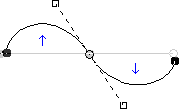
Les segments courbes peuvent facilement se construire par un cliquer-glisser sur le segment. Des tangentes sont créées sur les nœuds des extrémités et, en appuyant sur Maj, les poignées resteront symétriques et vous pourrez agir aussi sur les segments adjacents.
![[Astuce]](images/tip.png)
Astuce To quickly close the curve, click on the initial control point. If you want to reposition the start node, hold Shift and click to deselect the end node, then move the start node.
You can use the button or
 the Path to Selection button
in the Paths dialog to convert the path to a Selection.
the Path to Selection button
in the Paths dialog to convert the path to a Selection.
Astuce Si vous maintenez la pression pendant la création d’un nouveau nœud, en glissant la souris vous créez les tangentes de ce nœud. Par défaut elles sont symétriques. Dés que vous relâchez la pression la symétrie est désactivée et vous pouvez finir de positionner les tangentes en bougeant leurs poignées. La touche Maj permettra de passer à nouveau à la symétrie des tangentes.
Several functions are available in Design mode:
Insertion d’un nouveau nœud : si vous appuyez sur Ctrl et passez le pointeur de la souris au dessus du chemin existant, le pointeur devient un signe +. Un clic crée alors un nouveau nœud à l’endroit du point survolé du chemin.
Déplacer un ou plusieurs nœud : si vous cliquez sur un nœud, celui-ci sera activé et le curseur prendra la forme de la croix de déplacement. Vous pouvez dès lors le déplacer en maintenant la pression et en glissant la souris. Vous pouvez sélectionner plusieurs nœuds en utilisant la touche Maj puis déplacer l’ensemble de ces nœuds en glissant la souris. La combinaison de touches Ctrl+Alt permet de déplacer l’ensemble du chemin comme une sélection.
Modifying handles: You have to Edit a node first. A handle appears. Drag it to bend the curve. Pressing Shift toggles to symmetric handles.
Modify segment: When the mouse pointer moves over a segment, it turns to a 4-arrows cross. Click and drag it to bend the segment. As soon as you move it, handles appear at both ends of the segment. Pressing the Shift key toggles to symmetric handles.
Adding a new subpath: When you press Shift and hover the mouse pointer outside the existing path, the mouse pointer starts displaying a square. Clicking will start a subpath that isn't connected to other curves, but is considered a part of the path.
- Edit (Ctrl)
-
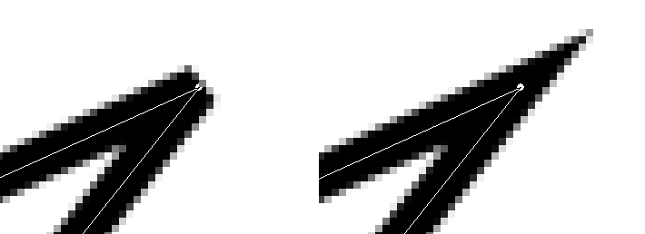
Edit performs functions which are not available in Design mode. With this mode, you can work only on the existing path. When the mouse pointer is not on the path, the pointer changes to a small crossed circle and you can not do any path editing.
Connecter deux nœuds par un segment : vous devez commencer par activer un nœud à l’extrémité d’un chemin, en cliquant dessus. Ensuite pointez vers le nœud qui est à l’autre extrémité du chemin. Le curseur prend la forme du symbole de l’union. Cliquez sur le nœud pour relier les deux nœuds.
Remove a segment from a path: While pressing Shift+Ctrl key combination, point to a segment. The mouse pointer turns to a "-" sign. Click to delete the segment.
Add a node to a path: point to a segment. Pointer turns to "+"". Click where you want to place the new control point.
Remove a node: While pressing Shift+Ctrl key combination, point to a node. Pointer turns to "-"". Click to delete the node.
Ajouter une tangente à un nœud : commencez par activer un nœud qui a au moins un coté anguleux, en cliquant dessus. Maintenez la pression et glissez avec la souris pour placer la nouvelle tangente. Avec la touche Maj vous pouvez imposer la symétrie des tangentes.
Remove a handle from a node: While pressing Shift+Ctrl key combination, point to a handle. The pointer doesn't turn to the expected "-"" and remains a hand. Click to delete the handle.
![[Attention]](images/caution.png)
Attention There is no warning before removing a node, segment or a handle.
- Move (Alt)
-
Avec le dernier mode Déplacer le chemin entier se laisse déplacer. Pour déplacer un chemin vous devez le sélectionner d’un clic de souris, maintenir la pression et glisser la souris.
If you have several components, only the selected one is moved. If you click and drag outside the path, all components are moved. Pressing the Shift key toggles between moving all components and selected components only.
- Polygonal
-
Avec cette option cochée les segments dessinés sont forcément rectilignes. Les nouveaux nœud ne comportent donc pas de tangentes et vous ne pouvez pas non plus créer de nouvelles tangentes.
- Selection from Path
-
This button allows creation of a selection that is based on the path in its present state. This selection is marked with the « marching ants » . Note that the path is still present: the current tool is still the path tool and you can modify this path without modifying the selection that has become independent. If you change tools, the path becomes invisible, but it persists in the Paths Dialog and you can re-activate it.
Si le chemin n’est pas fermé, GIMP en reliera les deux extrémités par une ligne droite.
As the help pop-up tells, pressing Shift when clicking on the button will add the new selection to an already existing one. Pressing Ctrl will subtract the selection from the pre-existing selection, and the Shift+Ctrl key combination will intersect the two selections.
- Create New Vector Layer
-
This command creates a Vector Layer from the current path. A vector layer remembers its stroke and fill settings and can have Layer Effects applied to it.
- Enable Fill
-
When checked the current path will be filled based on the settings below.
This setting only takes effect if the path being edited is attached to a vector layer. For filling paths not connected to a layer use Fill Paths.
- Solid color
-
If this is selected, you can choose what color is used to fill the path by pressing the color button.
- Pattern
-
If this is selected, a pattern will be used to fill the path. You choose another pattern by clicking the resource button or by typing the name of the pattern.
- Lissage
-
Enabling this setting allows you to remove or reduce the aliasing effect that can show up on borders.
For more information, see Anti-aliasing in the Glossary.
- Enable Stroke
-
When checked the current path will be stroked based on the settings below.
This setting only takes effect if the path being edited is attached to a vector layer. For stroking paths not connected to a layer use Stroke Paths.
- Solid color
-
If this is selected, you can choose what color is used to stroke the path by pressing the color button.
- Pattern
-
If this is selected, a pattern will be used to stroke the path. You choose another pattern by clicking the resource button or by typing the name of the pattern.
This is distinct from the Dash pattern. If you select one of the two color options with no dash pattern, an unbroken line is drawn in the color set in the Toolbox. If you select Pattern with no dash pattern, an unbroken line is drawn with the pattern set in the Toolbox. If you select a line with a dash pattern, the color or pattern is still determined by the color or pattern set in the Toolbox. That is, if you have a marbled pattern set in the Toolbox, and select Pattern and dashed lines as Dash pattern, the dashes are drawn in the marbled pattern.
- Lissage
-
Enabling this setting allows you to remove or reduce the aliasing effect that can show up on borders.
Curved strokes or strokes drawn at an angle may look jagged or stair-stepped. The anti-aliasing option smooths them out.
For more information, see Anti-aliasing in the Glossary.
- Line width
-
You can set the width of the stroke using the text box. The default unit is pixels, but you can choose another unit with the drop-down list button.
- Cap style
-
Choose the shape of the ends of an unclosed path, which can be Butt, Round or Square.
- Join style
-
You can choose the shape of the path corners by clicking on Miter, Round or Bevel.
- Miter limit
-
When two segments of a path come together, the mitering of the corner is determined by the Miter Limit. If the strokes were wide, and no mitering were done, there would be pointed ends sticking out at the corner. The Miter Limit setting determines how the gap, formed when the outer edges of the two lines are extended, will be filled. You can set it to a value between 0.0 and 100.0, by using the slider or the associated text box and its arrows.
- Dash pattern
-
On the pixel level, a dashed line is drawn as a series of tiny boxes. You can modify the pattern of these boxes. The black area with thin vertical lines represents the pixels of the dash. If you click on a black pixel, you remove it from the dash. If you click on a white pixel, you add it to the dash. The gray areas indicate how the pattern will be repeated when a dashed line is drawn.
- Dash preset
-
Instead of making your own dash pattern, you can choose one from the drop-down box. This pattern will then be displayed in the Dash pattern area, so you can get an idea of how it will look.
When right-clicking on path elements, like anchors or segments, a context menu will appear, the contents of which depends on the item you clicked on. The following commands may be shown in the context menu.
- Delete Anchor
-
This command deletes the selected anchor and connects the segments before and after it.
- Shift Start
-
This command shifts the start anchor to the selected anchor. The start anchor is where stroking starts. The start anchor has a pointy side indicating the stroking direction. This can be useful when you want to wrap Text along Path.
Shifting the start anchor on open strokes may insert a new segment connecting the previous endpoints, and removes the segment leading into the new start anchor.
- Insert Anchor
-
This command adds a new anchor on the selected spot on the segment.
- Delete Segment
-
This command deletes the selected segment. This will create an opening in your path.
- Reverse Stroke
-
This reverses the direction of the stroke. The shape of the start anchor will reflect the direction of the stroke. The pointy side is the direction it will go to when stroking.


