The Paths tool allows you to create complex geometric shapes called 「Bézier Curves」, a bit like the Free Selection tool, but with all the adaptability of vectorial curves.
You can edit your curve, you can paint with your curve, or even save, import, and export the curve. You can also use paths to create geometrical figures. Paths have their own dialog box: the Paths Dialog.
See also the Paths concept.
Paths can be turned into Vector layers. A Vector layer is a special kind of layer that displays a path, possibly consisting of several parts, including their selected fill and stroke attributes.
There are different possibilities to activate the tool:
-
From the main menu: → .
-
By clicking the tool icon
 in the Toolbox.
-
By pressing the B keyboard shortcut.
![[注記]](images/note.png)
|
注記 |
|---|---|
|
The status bar at the bottom of the image window will show relevant tips about the possible modifiers you can use when working with paths. |
- Shift
-
このキーには脈絡に沿ってさまざまな機能が付与されます。 詳細はツールオプションをご覧ください。
- Ctrl ; Alt
-
パスツールの作業モードは 作成、 編集、 移動 の 3 種類に分かれます。 Ctrl キーを押すと作成モードから編集モードに切り替わります。 Alt (あるいは Ctrl+Alt ) を押すと作成モードから移動モードに切り替わります。
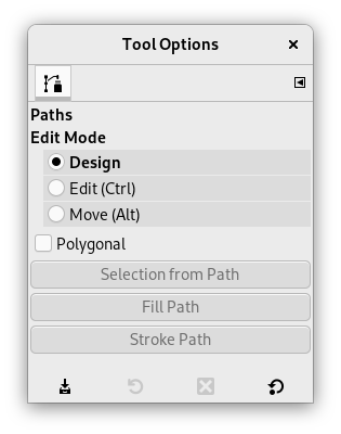
Normally, tool options are displayed in a window attached under the Toolbox as soon as you activate a tool. If they are not, you can access them from the main menu through → → which opens the option window of the selected tool.
- 編集モード
-
- Design
-
このツールの既定モードは 作成 です。 つぎつぎと画像上をクリックしてパスを描いてゆきます。 置かれたコントロールポイントはクリックしてドラッグすれば移動できます。 各コントロールポイントの間にあるのが分節です。

打たれた番号は 2 つの分節からなる直線パスを描く順序である。
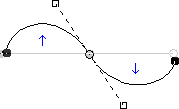
曲がった分節を作るにはただその分節をドラッグするか新たなアンカーをドラッグすればよい。 青の矢印で曲がるところを指し示した。 2 つの小さなハンドルが出現したので、 あとはそれをドラッグしても曲線を曲げ直せる。
![[ヒント]](images/tip.png)
ヒント To quickly close the curve, click on the initial control point. If you want to reposition the start node, hold Shift and click to deselect the end node, then move the start node.
You can use the button or
 the Path to Selection button
in the Paths dialog to convert the path to a Selection.
the Path to Selection button
in the Paths dialog to convert the path to a Selection.
ヒント 初期設定ではハンドルを 2 つもつと対称的に動作します。 ハンドルを個別に操作するときは一旦マウスボタンを放します。 Shift キーを押しながらの操作なら再びハンドルは点対称に動きます。
Several functions are available in Design mode:
Inserting a new node: When you press Ctrl and hover the mouse pointer over the existing path, the mouse pointer changes to the '+' sign. Clicking will create a new path node in the hovered point of the path.
Moving one or several nodes: On a node, the mouse pointer becomes a 4-arrows cross. You can click and drag it. You can select several nodes by Shift and click and move them by click and drag. Pressing Ctrl+Alt allows to move all the path, as a selection.
Modifying handles: You have to Edit a node first. A handle appears. Drag it to bend the curve. Pressing Shift toggles to symmetric handles.
Modify segment: When the mouse pointer moves over a segment, it turns to a 4-arrows cross. Click and drag it to bend the segment. As soon as you move it, handles appear at both ends of the segment. Pressing the Shift key toggles to symmetric handles.
Adding a new subpath: When you press Shift and hover the mouse pointer outside the existing path, the mouse pointer starts displaying a square. Clicking will start a subpath that isn't connected to other curves, but is considered a part of the path.
- Edit (Ctrl)
-
Edit performs functions which are not available in Design mode. With this mode, you can work only on the existing path. When the mouse pointer is not on the path, the pointer changes to a small crossed circle and you can not do any path editing.
2 つの終端アンカーを繋ぐ分節を追加 - パスの終端アンカーをクリックして活性化します。 マウスポインターには小さな連結のしるし (重なった 2 つの円) がつきます。 もう一方の終端アンカーをクリックすると両者は連結されます。 閉じていない成分を繋ぎ合わせる用途に向いています。
Remove a segment from a path: While pressing Shift+Ctrl key combination, point to a segment. The mouse pointer turns to a "-" sign. Click to delete the segment.
Add a node to a path: point to a segment. Pointer turns to "+"". Click where you want to place the new control point.
Remove a node: While pressing Shift+Ctrl key combination, point to a node. Pointer turns to "-"". Click to delete the node.
アンカーにハンドルを追加 - アンカーの上ではマウスポインターの右上に小さな四方矢印がつきます。 アンカーをクリックすると、 ハンドルが (削除されていなければ) 現れます。 もしひとつだけだったり全く無かった場合はアンカーをドラッグすればハンドルが現れます。アンカーには 2 つまでハンドルがつけられます。 ハンドルがひとつだけの場合には Shift キーを押しながらそのハンドルをドラッグすればもう一方のハンドルが点対称の位置に現れます。
Remove a handle from a node: While pressing Shift+Ctrl key combination, point to a handle. The pointer doesn't turn to the expected "-"" and remains a hand. Click to delete the handle.
![[注意]](images/caution.png)
注意 There is no warning before removing a node, segment or a handle.
- Move (Alt)
-
移動 モードでは 1 面のパスのひとつもしくは複数の成分を移動できます。 そのままパスをクリックしてドラッグしてください。
If you have several components, only the selected one is moved. If you click and drag outside the path, all components are moved. Pressing the Shift key toggles between moving all components and selected components only.
- 多角形
-
このオプションを指定すると描ける分節は直線のみになります。 ハンドルは使えません。 分節をドラッグすると変形しないで移動をします。
- Selection from Path
-
This button allows creation of a selection that is based on the path in its present state. This selection is marked with the 「marching ants」 . Note that the path is still present: the current tool is still the path tool and you can modify this path without modifying the selection that has become independent. If you change tools, the path becomes invisible, but it persists in the Paths Dialog and you can re-activate it.
閉じていないパスを変換した場合は、 各成分ごとに始点と終点が直線で結ばれて閉じられます。
As the help pop-up tells, pressing Shift when clicking on the button will add the new selection to an already existing one. Pressing Ctrl will subtract the selection from the pre-existing selection, and the Shift+Ctrl key combination will intersect the two selections.
- Create New Vector Layer
-
This command creates a Vector Layer from the current path. A vector layer remembers its stroke and fill settings and can have Layer Effects applied to it.
- Enable Fill
-
When checked the current path will be filled based on the settings below.
This setting only takes effect if the path being edited is attached to a vector layer. For filling paths not connected to a layer use Fill Paths.
- Solid color
-
If this is selected, you can choose what color is used to fill the path by pressing the color button.
- Pattern
-
If this is selected, a pattern will be used to fill the path. You choose another pattern by clicking the resource button or by typing the name of the pattern.
- なめらかに
-
Enabling this setting allows you to remove or reduce the aliasing effect that can show up on borders.
For more information, see Anti-aliasing in the Glossary.
- Enable Stroke
-
When checked the current path will be stroked based on the settings below.
This setting only takes effect if the path being edited is attached to a vector layer. For stroking paths not connected to a layer use Stroke Paths.
- Solid color
-
If this is selected, you can choose what color is used to stroke the path by pressing the color button.
- Pattern
-
If this is selected, a pattern will be used to stroke the path. You choose another pattern by clicking the resource button or by typing the name of the pattern.
This is distinct from the Dash pattern. If you select one of the two color options with no dash pattern, an unbroken line is drawn in the color set in the Toolbox. If you select Pattern with no dash pattern, an unbroken line is drawn with the pattern set in the Toolbox. If you select a line with a dash pattern, the color or pattern is still determined by the color or pattern set in the Toolbox. That is, if you have a marbled pattern set in the Toolbox, and select Pattern and dashed lines as Dash pattern, the dashes are drawn in the marbled pattern.
- なめらかに
-
Enabling this setting allows you to remove or reduce the aliasing effect that can show up on borders.
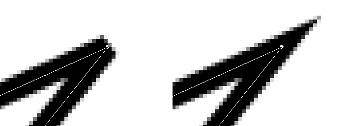
Curved strokes or strokes drawn at an angle may look jagged or stair-stepped. The anti-aliasing option smooths them out.
For more information, see Anti-aliasing in the Glossary.
- Line width
-
You can set the width of the stroke using the text box. The default unit is pixels, but you can choose another unit with the drop-down list button.
- Cap style
-
Choose the shape of the ends of an unclosed path, which can be Butt, Round or Square.
- Join style
-
You can choose the shape of the path corners by clicking on Miter, Round or Bevel.
- Miter limit
-
When two segments of a path come together, the mitering of the corner is determined by the Miter Limit. If the strokes were wide, and no mitering were done, there would be pointed ends sticking out at the corner. The Miter Limit setting determines how the gap, formed when the outer edges of the two lines are extended, will be filled. You can set it to a value between 0.0 and 100.0, by using the slider or the associated text box and its arrows.
- Dash pattern
-
On the pixel level, a dashed line is drawn as a series of tiny boxes. You can modify the pattern of these boxes. The black area with thin vertical lines represents the pixels of the dash. If you click on a black pixel, you remove it from the dash. If you click on a white pixel, you add it to the dash. The gray areas indicate how the pattern will be repeated when a dashed line is drawn.
- Dash preset
-
Instead of making your own dash pattern, you can choose one from the drop-down box. This pattern will then be displayed in the Dash pattern area, so you can get an idea of how it will look.
When right-clicking on path elements, like anchors or segments, a context menu will appear, the contents of which depends on the item you clicked on. The following commands may be shown in the context menu.
- Delete Anchor
-
This command deletes the selected anchor and connects the segments before and after it.
- Shift Start
-
This command shifts the start anchor to the selected anchor. The start anchor is where stroking starts. The start anchor has a pointy side indicating the stroking direction. This can be useful when you want to wrap Text along Path.
Shifting the start anchor on open strokes may insert a new segment connecting the previous endpoints, and removes the segment leading into the new start anchor.
- Insert Anchor
-
This command adds a new anchor on the selected spot on the segment.
- Delete Segment
-
This command deletes the selected segment. This will create an opening in your path.
- Reverse Stroke
-
This reverses the direction of the stroke. The shape of the start anchor will reflect the direction of the stroke. The pointy side is the direction it will go to when stroking.


