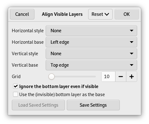
С помощью команды можно точно поместить относительно друг друга видимые слои изображения (те, что помечены значком «глаза»). Точность расположения особенно полезна при работе с анимацией, где обычно много маленьких слоёв. Команда открывает диалог, позволяющий указать, как следует выровнять слои.
-
Получить доступ к этой команде можно через меню изображения → . Комбинация клавиш по умолчанию не присвоена. Если изображение содержит только один слой, GIMP выведет сообщение о том, что для выполнения команды в изображении должен присутствовать по крайней мере один слой.
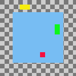
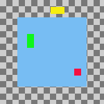
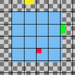
The examples in the Description of the “Align Visible Layers” dialog section all use the same starting image. The image contains four layers. The order of those layers from top to bottom is as follows:
-
Green, vertical rectangle (top layer)
-
Yellow, horizontal rectangle
-
Red, small square
-
Blue, larger square (bottom layer)

The command aligns layers based on their boundaries. In the example image, each layer's boundary is adjusted to match the perimeter of the shape in that layer. For information about how to adjust a layer's boundary, see Layer Boundary Size. You can also use a command such as Crop Layers to Content to automatically adjust a layer's boundary.
![[Примечание]](images/note.png)
|
Примечание |
|---|---|
|
In the examples, the Ignore the bottom layer even if visible checkbox is left checked. The bottom layer, which is the larger blue square, is then not affected by any of the alignment operations. |
- Горизонтальный стиль, Вертикальный стиль
-
Эти параметры определяют то, как будут передвинуты слои относительно друг друга. Даётся выбор:
-
Нет: не будет никаких изменений в горизонтальном или вертикальном положении, соответственно.
-
Собрать: видимые слои будет выровнены на холсте согласно параметрам Горизонтальное основание и Вертикальное основание. Если выбрать значение Правый край параметра Горизонтальное основание, то слои могут исчезнуть за пределами холста. Их можно вернуть, увеличив размер холста. При выборе параметра Использовать (невидимый) нижний слой как основание слои выровняются по левому верхнему углу нижнего слоя.
Рисунок 16.73. Example Use of Collect: Layers Aligned to Left Edge of the Canvas
Исходное изображение
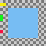
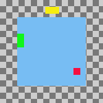
Horizontal style: Collect , Horizontal base: Left edge.
Слои были передвинуты горизонтально так, что их левые края выровнялись по левому краю холста.
Рисунок 16.74. Example Use of Collect: Layers Aligned to Left Edge of the Bottom Layer
Исходное изображение
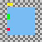
Same parameters as the previous example, but with the Use the (invisible) bottom layer as the base checkbox checked.
Слои были передвинуты горизонтально так, что их левые края выровнялись по левому краю нижнего слоя.
-
Fill (left to right); Fill (top to bottom): The visible layers will be arranged left to right (or top to bottom) on the canvas according to their order in the layer stack.
The top layer in the stack will be aligned with the layer that currently has the leftmost (or uppermost) position on the canvas. The bottom layer in the stack will be aligned with the layer that currently has the rightmost (or bottommost) position on the canvas. All other visible layers will be evenly distributed between those two positions according to their order in the layer stack.
Your choice of Horizontal base (or Vertical base) determines how the top and bottom layers are aligned with their respective target layers. For example, if you choose Right edge as the Horizontal base, the right edge of the top and bottom layers will be aligned with the right edge of their target layers.
Примечание If the Use the (invisible) bottom layer as the base checkbox is checked, the top layer in the stack will be aligned with the current position of the bottom layer in the stack, instead of the leftmost (or uppermost) layer on the canvas.
Рисунок 16.75. Example Use of Fill: Layers Filled Left to Right
Исходное изображение
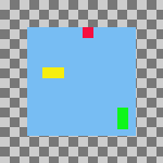
Horizontal style: Fill (left to right), Horizontal base : Left edge.
The top layer in the stack, the green one, was aligned with the layer that had the leftmost position on the canvas. The bottom layer in the stack, the red one, was aligned with the layer that had the rightmost position on the canvas. The yellow layer is placed between the other two.
Рисунок 16.76. Example Use of Fill: Layers Filled Left to Right With the Bottom Layer as the Base
Исходное изображение
Same parameters as the previous example, but with the Use the (invisible) bottom layer as the base checkbox checked.
The top layer in the stack, the green one, is aligned with the left edge of the base layer. The bottom layer in the stack, the red one, was aligned with the layer that had the rightmost position on the canvas. The yellow layer is placed between the other two.
-
Заполнить (справа налево); Заполнить (снизу вверх): эти параметры похожи на предыдущие, но заполнение происходит в противоположном направлении.
Рисунок 16.77. Example Use of Fill: Layers Filled Bottom to Top With the Bottom Layer as the Base
Исходное изображение
Vertical style: Fill (bottom to top), Vertical base : Top edge, Use the (invisible) bottom layer as the base: checked.
The bottom layer in the stack, the red one, is aligned with the top edge of the base layer. The top layer in the stack, the green one, was aligned with the top edge of the of the layer that had the lowest position on the canvas. The yellow layer is placed between the other two.
Необходимо по меньшей мере три слоя, чтобы воспользоваться параметрами группы «Заполнить».
-
Прилипать к сетке: видимые слои будут выровнены по сетке. Используйте параметр Сетка, чтобы определить расстояние между линиями сетки. Выбранное основание будет выровнено по ближайшей к нему линии сетки. Например, если выбрать значение Левый край из списка Горизонтальное основание, левый край каждого слоя будет выровнен по линии сетки, которая находится ближе всего к левому краю слоя.
В следующем примере сетка изображения включена, и расстояние между её линиями имеет то же значение, что и параметр Сетка. Это сделано только для того, чтобы продемонстрировать эффект от использования опции Прилипать к сетке. Нет необходимости включать сетку изображения, и ни один из её параметров не используется при выравнивании слоёв.
Рисунок 16.78. Example Use of Snap to Grid: Layers Aligned to Top Left Corner of Grid Squares
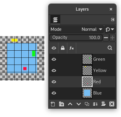
Original image with an added 30 pixel image grid
Horizontal style: Snap to grid, Horizontal base: Left edge, Vertical style : Snap to grid, Vertical base: Top edge , Grid: 30
Each layer other than the base is aligned with the top left corner of a 30 by 30 pixel grid square.
-
- Сетка
-
Если выбрать опцию Прилипать к сетке из списка Горизонтальный стиль или Вертикальный стиль, параметр Сетка определяет расстояние между линиями сетки, по которой выравниваются слои.


