| 5. Paths | ||
|---|---|---|
 |
Chapter 7. Painting with GIMP |  |
| 5. Paths | ||
|---|---|---|
| |
Chapter 7. Painting with GIMP | |
Paths are curves (known as Bézier-curves). Paths are easy to learn and use in GIMP. To understand their concepts and mechanism, look at the glossary Bézier-curve or Wikipedia [WKPD-BEZIER]. The Paths tool is very powerful, allowing you to design sophisticated forms. To use the Paths tool in GIMP, you must first create a path, and then stroke the path.
In GIMP, the term “Stroke path” means to apply a specific style to the path (color, width, pattern... ).
A Path has two main purposes:
You can convert a closed path to a selection.
Any path, open or closed, can be stroked; that is, painted on the image in a variety of ways.
Figure 7.10. Illustration of four different path creating
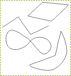
Four examples of GIMP paths: one closed and polygonal; one open and polygonal; one closed and curved; one with a mixture of straight and curved segments.
Start by drawing the outline for your path; the outline can be modified later (see the Paths tool). To start, select the Paths tool using one of the following methods:
Use → from the image menu.
Use the relevant icon
 in toolbox.
Use the hotkey B.
When the Paths tool is selected, the mouse cursor changes into a pointer (arrow) with a curve. Left click in the image to create the first point on the path. Move the mouse to a new point and left click the mouse to create another point linked to the previous point. Although you can create as many points as you desire, you only need two points to learn about Paths. While adding points, the mouse cursor has a little “+” next to the curve, which indicates that clicking will add a new point. When the mouse cursor is close to a line segment, the “+” changes into a cross with arrows; like the move tool.
Move the mouse cursor close to a line segment, left-click and drag the line segment. Two events occur.
The line segment bends and curves as it is pulled.
Each line segment has a start point and an end point that is clearly labeled. A “direction line” now projects from each end point for the line segment that was moved.
The curved line segment leaves an end point in the same direction that the “direction line” leaves the end point. The length of the “direction line” controls how far the line segment projects along the “direction line” before curving toward the other end point. Each “direction line” has an empty square box (called a handle) on one end. Click and drag a handle to change the direction and length of a “direction line”.
Figure 7.11. Appearance of a path while it is manipulated
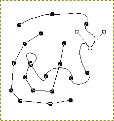
Appearance of a path while it is manipulated using the Path tool.
The path is comprised of two components with both straight and curved segments. Black squares are anchor points, the open circle indicates the selected anchor, and the two open squares are the handles associated with the selected anchor.

