| 4. 변형 도구 | ||
|---|---|---|

|
14장. 도구 |  |
Inside the Transformation tool dialog, you will find eight tools to modify the presentation of the image or the presentation of an element of the image, selection, layer or path. Each transform tool has an Option dialog and an Information dialog to set parameters.
Some options are shared by several transform tools. We will describe them here. More specific options will be described with their tool.
GIMP offers you three buttons which let you select which image element the transform tool will work on.
![[참고]](images/note.png)
|
참고 |
|---|---|
|
Remember that the Transform option persists when you quit the tool. |
When you activate the first button
 the tool works on the active layer. If no selection exists in
this layer, the whole layer will be transformed.
When you activate the second button
 the tool works on the selection contour only (the whole layer
contour if no selection).
When you activate the third button,
 the tool works on the path only.
This option sets which way or direction a layer is transformed:
The “Normal (Forward)” mode will transform the image or layer as one might expect. You just use the handles to perform the transformation you want. If you use a grid (see below), the image or layer is transformed according to the shape and position you put the grid into.
“Corrective (Backward)” inverts the direction. Primarily used with the Rotation tool to repair digital images that have some geometric errors (a horizon not horizontal, a wall not vertical...). See 4.5절. “Rotate”.
This drop-down list lets you choose the method and thus the quality of the transformation:
The color of each pixel is copied from its closest neighboring pixel in the original image. This often results in aliasing (the “stair-step” effect) and a coarse image, but it is the fastest method. Sometimes this method is called “Nearest Neighbor”.
The color of each pixel is computed as the average color of the four closest pixels in the original image. This gives a satisfactory result for most images and is a good compromise between speed and quality. Sometimes this method is called “Bilinear”.
The color of each pixel is computed as the average color of the eight closest pixels in the original image. This usually gives a good result, but it naturally takes more time. Sometimes this method is called “Bicubic”.
The Lanczos3 method uses the Sinc mathematical function and performs a high quality interpolation. This is usually the best method but if you are not satisfied with the result, you may give “Cubic” a try.
You can set the default interpolation method in the Tools Options Preferences dialog.
After transformation, the image can be bigger. This option will clip the transformed image to the original image size.
You can choose between several ways to clip:
그림 14.102. Original image for examples

원본 이미지

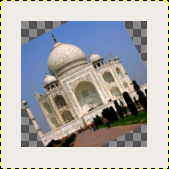
Rotation applied with “Adjust”

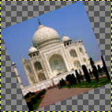
Rotation applied with “Adjust” and canvas enlarged to layer size
With Adjust: the layer is enlarged to contain all the rotated layer. The new layer border is visible; the whole layer becomes visible by using the → command.
With Clip: all what exceeds image limits is deleted.
그림 14.104. Example for Crop to result

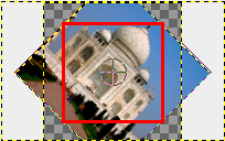
Rotation 45° with Crop to result

The crop limit is marked with red. No transparent area is included.
If this option is selected, the image is cropped so that the transparent area, created by the transform operation in corners, will not be included in the resulting image.
This option works like the one described before, but makes sure, that the aspect ratio is maintained.
If this is marked, which is the default setting, the transformed image will be visible on top of the original image or layer. There will also be a slider with which you may select the preview opacity.
This is a drop down list where you select the type of guide lines which suits your transforming. All the guides uses a frame to mark the image's outline in addition to the lines used by the different selections.
As the name tells you, there are no guides used.
Uses one vertical line and one horizontal line crossing each other in the center of the image or layer.
Divides the transforming area in nine equal parts by adding two horizontal lines and two vertical lines equally spaced. According to this rule the most interesting parts of the image should be placed at the intersection points.
Just as the “Rules of thirds” but divides the area in five by five parts.
Also called “The Golden Ratio”. This divides the transforming area in nine parts using a mathematical formula proportioning the parts to each others and to the area to be transformed.
Divide the transforming area using diagonally lines.
Puts a rectangular grid with equal numbers of vertically and horizontally lines. The number of lines is set in the slider popping up when this guide is selected.
Puts a rectangular grid on the transforming area using the spacing between the lines set in the slider.
If you for some reason want to transform paths, it is possible to do this using the transform tools.
When the path is drawn go to the path dialog and click on the first field before the path outline in the dialog window to get the eye icon visible. Then choose the transformation tool and in the upper part of the option dialog click on the path icon to tell the tool to act on the path.
Do the transformation the usual way and confirm it when finished. It could be a good idea to set the Guides to “No guides” to get the path more recognizable.
When the transformation is finished, choose the path tool and click on the changed path to activate it again for further working on it.